

888-848-0499
Moving Heavy Loads
Successfully Moving Heavy Loads With Machine Skates
Includes Several Important Technical and Planning Factors

Loading Capacity
All our machine skates offer multiple loading capacity options within each style and model. Loading capacity is defined as the maximum load (expressed in Imperial Tons) that the particular model/unit is designed to support when LOADED AND USED PROPERLY. When loaded within the specified loading capacity and used properly, the user can expect the performance and maneuvering capabilities detailed for each model and style of the machine skate.
SAFETY & PROPER USE
Always inspect machine skates, rollers, connecting bars, and related components before each use for damage, excessive wear, irregularities, or other conditions that may hinder or degrade safe performance. Do not use damaged or unsafe equipment.
NEVER EXCEED the rated load capacity of the machine skate model being used.
The user is responsible for selecting the appropriate number, capacity, placement, and configuration of machine skates for the load being moved. Combined rated capacity alone does not establish that a particular configuration is safe or suitable.
Loads must be placed only on the designated load-bearing area of the machine skates.
Loads must be lowered slowly and gently onto the machine skates.
NO SHOCK LOADING. Never drop or rapidly lower a load onto the machine skates.
Loads must be evenly distributed across all machine skates used in the transporting configuration.
Machine skates must be operated only on a suitable, stable, level surface capable of supporting the combined weight of the load and equipment.
Transporting or rolling speed of loaded machine skates MUST NOT EXCEED one (1) mile per hour (1 mph).
Never allow a load to tip, tilt, shift, or otherwise become unstable during placement or transport.
Always use the connecting bar when operating FT Fixed-Series machine skates.
NEVER place hands, arms, feet, head, or any other part of the body beneath a load.
Appropriate personal protective equipment, including safety footwear, head protection, and other equipment appropriate for the operation, must be worn.
All applicable workplace safety procedures, regulations, and OSHA requirements for lifting, moving, rigging, and transporting heavy loads must be followed.
Machine skates and heavy-load-moving equipment should be used only by persons possessing the appropriate training, knowledge, and experience. Qualified rigging or heavy-machinery professionals should be utilized whenever the user does not possess the necessary expertise or experience.
Complete Safety, Warranty & Liability Information
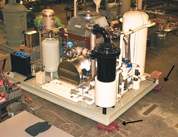
Performance Under Loading
All models of our machine skates are designed to perform a particular function and each style has a range of maneuvering characteristics unique to that model. All of our models utilize Durable Urethane Rollers for floor protection. Consequently, there is a tradeoff between the “give” of the roller and the urethane hardness necessary to support tons of loading.
Simply put, the heavier the load, the harder it will be to turn and move. This is obviously mostly related to the fact that a heavier weight requires a larger force to maneuver it. In the case of machine skates with urethane rollers there is also the factor that a larger load flexes and compresses the urethane rollers more against the floor (see below for a full discussion of floor pressure calculations.) From a floor protection standpoint, the flexing and compressing characteristic is beneficial as it spreads the load over a slightly larger roller footprint on the flooring surface.
However, the flexing and compressing roller, in its loaded state, also increases the friction resistance against the flooring surface when maneuvering the load with the skates. Because of the flexing and compressing urethane rollers, the closer each unit is loaded towards its maximum loading capacity, the more force it will take to maneuver that load. Again, additional force is primarily required because the load is heavier, but some of the required increase in force is also because the urethane rollers are flexing and compressing more under the increased weight.
Our heavy machine dollies are built to maneuver and perform at the high end of their loading capacity. However, the force needed to turn and move loads when the skates are loaded at their maximum loading capacity can be substantial. Maneuvering performance with the least relative effort will be when a particular model is loaded lightly compared to its maximum loading capacity. Maneuvering performance with the most relative effort will occur when a particular model is loaded at its maximum loading capacity.

Load Weight & Distribution
A user should never enter into any kind of machine moving project without knowing the weight of the load to be transported. It is also critical to understand how the weight of the load is distributed across the load footprint. Not knowing the weight and distribution footprint of a load can be dangerous. It can lead to an overloaded condition which can damage the machine skates and possibly even the load itself.
Most loads that will be moved will be somewhat symmetrical in their weight profile, meaning the weight of the load will be distributed fairly evenly across its footprint. Sometimes though, it may be necessary to allow for the load being significantly heavier or lighter on one end/side or the other. One possibility to solve this issue may be to use different loading capacity skates on the respective ends/sides of the load. However, the best solution is usually to utilize models that offer plenty of loading capacity so there is a margin for error.
Another aspect of moving a heavy load, is to understand the dynamics of the load being transported across a flooring surface that is slanted. The user should keep in mind that a load that moves from a relatively flat surface to a slanted one, will put more weight and stress on the “downhill” side of the load. As such, the loading capacity of the “downhill” skates should be adequately sized to handle the additional weight that a slanting floor will place on those particular skates.

Lifting the Load
Methods for lifting and raising the load "up" so the machine skates can be positioned underneath include hydraulic jacks, toe jacks, forklifts, overhead cranes and winch systems among others. Our machine skates are made with a Low Profile, Low Clearance Design in order to minimize the distance a load must be lifted in order to position the skates underneath.
We distribute a bottle-style series of Hydraulic Toe Jacks which have proven effective and efficient in lifting equipment and machinery. The bottle style Toe Jack is an economical, but still rugged, lifting option with a fixed toe.

Points of Contact
How many points of contact are necessary to properly distribute the weight of a load? The short answer is however many it takes for a particular situation. Factors such as the overall load weight, the load footprint, the load dimensions, the rigidity of the bottom structure of the load and so on will all have to be analyzed to formulate and complete a successful move.
Our various styles of machine skates provide a range of configuration options. Most of the time, loads can be moved with the tried and true, classic SFT 3-Point System or the popular, maximum maneuverability option of (4) RT Rotating Models. Since all styles and models of our skates are made with the same 4.25 inch height, there are numerous mix and match configuration options available.

Force Needed to Maneuver a Load
Once a load is lowered onto the machine skates there must be sufficient means to turn, move and maneuver the load. For lighter loads, as a broad rule of thumb, one person can move around 2 tons on a smooth, level, debris-free surface. As the weight of the load increases, it will take significantly more manpower and horsepower (usually forklifts, power pushers, winches, etc.) to successfully maneuver and position the heaviest loads.
For loads on level, smooth, debris-free concrete, a fair approximation would be to assume each Roller (in any of the configurations), fully loaded, takes approximately 40 lbf of force to continuously roll the load. It will take roughly 20% more force per roller (~50 lbf) to produce enough breakaway force to get the load moving from a static position.
So, for example, a fully loaded ST-4 (8,000 lb max load) with 4 rollers would take around 200 lbf of force to breakaway and 160 lbf of force to keep the load in motion. At the other end of the load spectrum, a SFT-64 (128,000 lb max load) with 48 rollers would take 2,400 lbf of force to breakaway and 1,920 lbf of force to keep the load in motion.
Again, note that these are rough figures for smooth, level, debris-free concrete. Any increase in incline or surface roughness will obviously increase the force needed to move heavy loads.
Most of the models of the heavy machine skates that we manufacture are expected to be used under fairly large loads, so a significant means of power to push, pull and maneuver the heavy load is almost always necessary. Again, options such as forklifts, power pushers, tractors and winches are popular options for applying a moving force. SFT, ST and RT models all provide a means to pull/push a load utilizing the Heavy Duty Handle & Eye Hook feature.

Space to Maneuver
The space available to turn and move a load after it is resting on the machine skates is another aspect of moving a heavy load that must be evaluated. The different styles and models of skates available (and how they are configured under the load) offer a range of maneuvering options as well.
IFT Single and FT Fixed models used alone provide the least maneuverability as they are limited to a straight-line motion. SFT 3-Point models provide an increased level of movement as the Steerable ST Unit gives the load configuration a steering component. Because of the design, there will still be a turning radius involved so adequate space to maneuver should be considered.
The most maneuverable configuration is to use multiple units of RT Rotating Series under the load. The RT Unit’s setup not only provides straight-line and radius turning, but also the added benefit of rotating and spinning. A heavy load can literally be moved in one direction, stopped, then moved in a 90 degree different direction. This type of turning and moving capability will be paramount when the space to maneuver is limited.

Floor Pressure
All machine skates we manufacture use the same size High-Quality, Durable Urethane Rollers which are 3.25 inches in diameter and 3.25 inches across in width. At any one time, a heavy load will flex and compress the rollers equating to an individual roller footprint area of approximately 1 to 1.25 square inches.
As the weight increases per roller, the flexing and compressing of each roller increases as well. Therefore, as the loading weight per roller increases, the rollers actually spread out the load over more surface area. The flexing and compressing characteristic of the urethane rollers help to protect the flooring surface by reducing the pressure per square inch on the flooring surface.
A simple calculation can be used to find the pressure transmitted per roller to the flooring surface.
Load Weight (lbs) divided by Number of Rollers divided by Roller Footprint Area (square inches) = Pressure per Roller (lbs/square inch or psi).
For example, the RT-8 Rotating Model fully loaded at 8 tons of maximum loading capacity would produce 2,560 psi of pressure per roller. The calculation would be:
8 tons or 16,000 lbs divided by 5 urethane rollers divided by a compressed 1.25 square inch footprint = 2,560 psi of pressure per roller on the flooring surface.

Rough Flooring Surfaces
The durable urethane rollers used on all machine skates we manufacture are designed to be non-marking and non-damaging to flooring surfaces. The rollers are fabricated with a high-quality, rugged urethane material designed to be long-lasting while still offering flexibility. Models, such as the FT Fixed Machine Skates, used consistently on smooth, debris-free flooring surfaces will last for many years. Most customers never need their urethane rollers replaced. A full discussion of the “just right” properties of our durable urethane roller can be found on the Key Features Page.
Use of the skates on rougher flooring surfaces will not affect the usefulness and performance of the rollers. However, over time, a rougher flooring surface will tend to pit and deteriorate the coating of the urethane rollers faster than a smoother flooring surface. Consistent and frequent use of the machine dollies on rougher, dirty flooring surfaces will decrease the life of the urethane rollers. When a roller's surface becomes too damaged to work effectively, we stock plenty of replacement rollers that can be quickly and conveniently replaced because of the Easy Bolt-On Axle Design Feature.

Flooring Surface Cracks and Ledges
One potential issue to keep in mind when using the Low-Profile, Low Clearance machine skates is that the durable urethane rollers are only 3.25 inches in diameter. Additionally, each roller has a footprint area of only 1 to 1.25 square inches depending how Flexed and Compressed they are. The small diameter rollers are key to a low profile design that limits the amount of clearance needed under a load to position the skates.
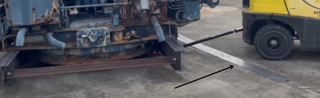
The tradeoff in the low profile design is that the skates are limited as to how much of a gap, crack, hole, etc. they can negotiate while moving a heavy load. Any crack in the flooring surface wider than a basic, normal concrete expansion joint can present problems. Excessive gaps and cracks can sometimes be overcome by rolling the skates over problem areas at an angle which will keep the urethane rollers from traversing the gap/crack at the same time. Other solutions include filling gaps/cracks with acceptable fillers to even out the transition area or using thin metal plating to bridge the gaps and cracks.
Another area of concern in the use of the low profile heavy machine skates is abrupt changes in the elevation of the flooring surface. For instance, this could be something like a crack in concrete flooring where one side has heaved up, forming a ledge, or an abrupt change in grade like a level floor transitioning to a ramp. The low clearance design of the skates means that the steel frames (SFT, ST, FT, IFT) and caster assemblies (RT) run very close to the ground so significant and abrupt flooring surface changes can prevent the skates from performing correctly. As discussed above, preventative steps should be taken by utilizing plating, fillers, etc. to make these transition points as gentle and subtle as possible.